

Abstract
In the industry, capacitor banks are used to reduce reactive loads, the arrangement of capacitor bank steps and the selection of the capacity of the first step are always the concern of panel makers. In the following article, the main and important points have been shared in this regard. to choose the best and most practical method
Introduction
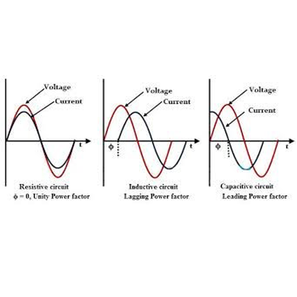
In distribution networks, we are faced with current drop from voltage and consumption of reactive load, therefore, at all times of loading, part of the consumed energy is taken out of the consumption cycle as reactive load. This power cannot be used and is wasted in the passage path at the same time, there are many losses for the network, the addition of the source current and as a result the need for sources with more powers, with the increase of the passing current, we need wires and cables with a higher cross-section, which increases the costs. Energy loss in wires and cables increases their temperature and reduces their useful life. Reactive power increases the current between the power source and consumers. In this way, the apparent power will increase and the power factor will decrease
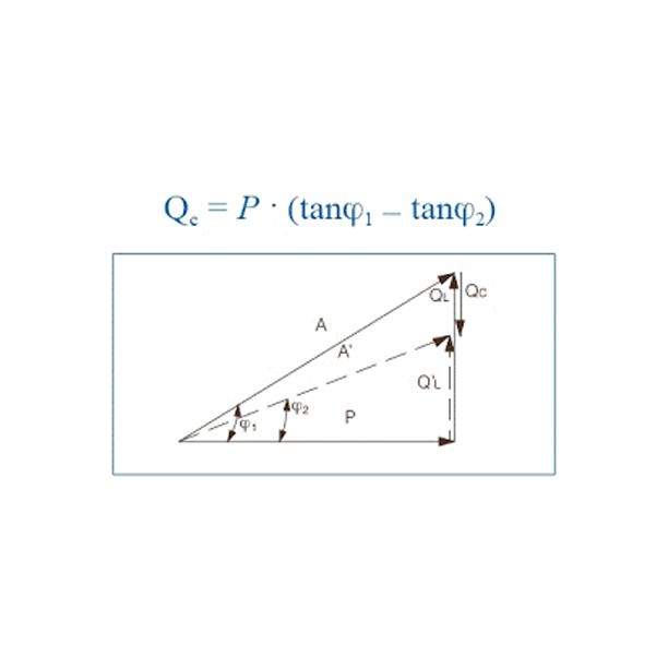
Correcting the power factor: This means that the required reactive power is produced at the load location instead of being supplied from power sources. In this case, the supply current has the lowest value and is able to supply the real power with a more constant voltage, and the current and voltage phased and the power factor should be close to one
Voltage regulation: changes in reactive power load to changes in voltage, compensating devices by producing reactive power causes relative stabilization of voltage against variable loads
Compensation with capacitor or micro capacitor
In order to compensate the reactive load and improve the power in the system, a capacitor bank is used, which is installed in parallel with other loads. Usually, in the industry, to reduce reactive loads, a centralized (central) capacitor bank is used at the beginning of the power input or near the distribution transformers. Installation and operation of capacitor bank panels on one hand and how to monitor its correct operation and how to periodically visit the installed equipment on the other hand will be very important in reducing energy losses and increasing the capacity of transformers and cables. He claimed that after transformers, capacitor bank panels are of special importance
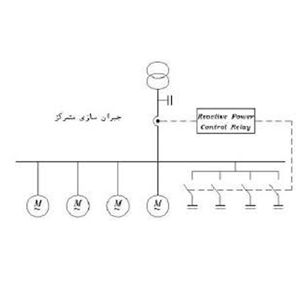
Central capacitor banks
The entire compensation system is installed and operated centrally at the beginning of the power input of the complex. In this method, all the reactive loads are corrected in one place and according to the reactive loads and the power factor, the capacitors are stepped into the circuit or out of the circuit. become This method is usually common in most countries and is considered the easiest way to install capacitors
Application
Correction of the first power factor of the line
Advantages
The whole system can be controlled and its installation is easy
Optimum use of installed capacitors
Reducing the number of capacitors due to the absence of the synchronicity factor
Disadvantages
This method is very popular due to the ease of installation, but it has many disadvantages for the network
First, the reactive power must be transferred from the same cable where the active power is transferred and reaches the consumers. As a result, the size of the energy transmission cables increases and causes an increase in costs. In addition, during the initial start of the motors, the capacitor bank regulator does not have the ability to enter suitable steps with the starting load, so practically it can be said that all the initial starts of the motors take place without the presence of the capacitor
In short, we can say
non-compensation within the network and imposing cable losses on the distribution network
Additional expenses for the design and construction of the automatic capacitor bank in the system
Failure to correct the voltage at the end of the line
Failure to correct the voltage and power factor of the motors during the initial start
Not reducing the current passing through the cables, switches and contactors during the initial start of the engines and under normal conditions.
However, due to the widespread use of this type of capacitor bank, the method of selecting the capacitor stages and the selection of the first stage for the arrangement of capacitors will be necessary
Determining the capacity of the first staircase and the arrangement of stairs
If the active and reactive load consumption information of the set or the power factor change curve is available, it is possible to obtain the capacity curve of the first step and the coefficients of the next steps by using the slope of the curve. Otherwise, according to the instructions and recommendations, it can be done in two ways. able to act
- A) If you need high accuracy with fast changes, which usually happens in small loads with large load changes, the first step can be started with 5% of the total capacity of the capacitor panel.
- b) If there is no need for accurate regulation (medium accuracy) or large load changes that usually happen at high powers with heavy electric motors, the first stage is selected with 10% of the total capacity.
The next steps, considering 5 or 10% of the total capacitor bank, can be at least equal to the previous step and at most equal to the sum of the previous steps plus the first step. It should be noted that it is better not to use stairs with a capacity of more than 100 K var in the construction of weak pressure banks
Arrangement of stairs
Of course, this method to find the capacity of the first step of micro capacitors is suitable for capacitor banks with low power, but it will be practically ineffective for capacitor banks with high power, for example: to determine the capacity of the first step of a capacitor bank with capacity Total 900 k var, including 5%, the first stage will be 45 k var, and taking into account 10%, the first stage will reach 90K Var, due to the arrangement of the capacitor bank, these numbers are unusual, so the best way to choose the first stage , determining the arrangement of the capacitor steps. With the determination of the capacitor steps and taking into account the coefficients mentioned below, the best option for choosing the first step is to use the coefficients of the arrangement of the steps.
Taking into account the fact that (in the selection of capacitors, it should be noted that smaller capacitors should be used as much as possible. The capacitor value of 12.5 k var is an optimal value)) capacitor steps can be designed accordingly. for example:
If you choose method 1.1.1.1, the best option is to choose 12.5 kVA capacitors
If you choose method 1.2.4.4, including capacitor 12.5 as the first step, the order of the steps will be like this. 50 / 50 / 25 / 12.5
If you choose arrangement 1.2.4.8, the order of stairs will be 100 / 50 / 25 / 12.5.
Considering the presented materials and the advantages and disadvantages of each arrangement of capacitor banks, it seems that the best and most common method of choosing capacitor banks is arrangement 1.2.4.4
Keywords
Capacitor bank panel, arrangement of capacitor steps, energy optimization. Reactive power compensation. micro capacitor Power factor correction